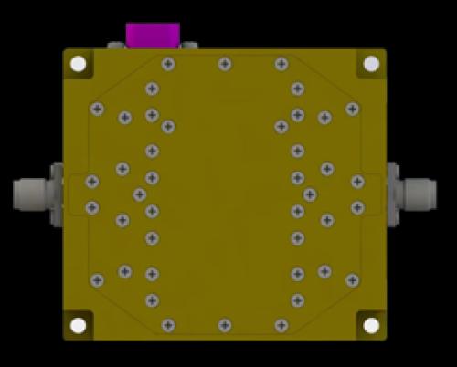

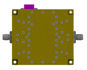
Ka band filter bank
Typical KA Airborne Frequency Filter Bank
|
KA Airborne Frequency Filter Bank Parameter |
Downlink IPDKADNFB_01 |
Uplink IPDKAUPFB_01 |
|
Frequency Band |
17.2-18.2GHz |
27.5-28.5GHz |
|
18.2-19.2GHz |
28.25-29.25GHz |
|
|
19.2-20.2GHz |
29-30GHz |
|
|
20.2-21.2GHz |
30-31GHz |
|
|
Insertion Loss |
-6dB Max |
|
|
Rejection |
30dB min@5% from edge |
|
|
Switching Speed TON / TOFF:50% control to 90% RF |
100ns max |
|
|
CW Power Handling/50% control to 90% RF |
29dBm Max |
|
|
Operation Temperature |
-40°C to +85°C |
|
|
Size(LxWxH) |
2.5x2.2x0.8 in |
|
|
63.5x56x20mm |
||
|
Control |
TTL |
|
|
DC |
+5.5V to +36V |
|
|
DC current |
70mA Max |
|
|
RF INPUT/OUTPUT |
2.92mm-K |
|
|
DC/CONTROL |
DB9(J30J-9ZK) |
|
DB9 Interface Definition Truth Table
|
Pin NO. |
Marking |
Definition |
Remark |
|
1 |
+12V |
Typical +12V |
+5.5V to +36V |
|
2 |
GND |
GND |
|
|
3 |
A0 |
Control 1 |
TTL/LVTTL |
|
4 |
A1 |
Control 2 |
TTL/LVTTL |
|
5~9 |
NC |
NC |
|
|
A1 |
A0 |
Band1 |
Band2 |
Band3 |
Band4 |
|
0 |
0 |
ON |
OFF |
OFF |
OFF |
|
0 |
1 |
OFF |
ON |
OFF |
OFF |
|
1 |
0 |
OFF |
OFF |
ON |
OFF |
|
1 |
1 |
OFF |
OFF |
OFF |
ON |
Description
Custom Switch filter banks
INDEPENDENT RF can design various products
tailored to customers' applications.
Only 3 Steps to Meet Your RF Passive Component
Needs:
2. Independent RF provides the design solution.
3. Independent RF completes customized
production.
1. Specify your parameter requirements.